Perimeter Loops – Area Coverage (maximum)
| Room aspect ratio |
1:1 |
2:1 |
3:1 |
| Maximum area m2 |
120 |
150 |
200 |
For any Induction Loop System, area coverage is dependent on several factors. Please check these assumptions and contact Ampetronic for advice if required:
- Loop must be 1-2m above or below the receiver height
- There should be no metal structures in the plane of the loop
- Sufficient voltage to drive the loop – check the cable table below
Maximum Cable Length
The ILD122 is designed for SINGLE TURN loops for optimum audio quality.
- Loops with DC resistance from 0.2 to 1.8Ω
- Impedance up to a maximum of 2.0Ω
Maximum cable length is dependent on cable type and on the application:
| Cable type |
Maximum Cable Length (m) |
|
Normal Use* |
Transient Speech* |
| 1.0mm2 copper |
76 |
87 |
| 2.5mm2 copper |
103 |
131 |
| 4.0mm2 copper |
108 |
140 |
| 1.8mm2 flat copper tape |
133 |
155 |
* Short term speech (e.g. service counter, airport PA system) can cope with limited clipping at high frequencies – Ampetronic recommends delivery of full current up to 1.2kHz for these applications.
Longer term usage or signals with music or high quality audio must deliver full current to at least 1.6kHz to prevent fatigue and give acceptable intelligibility. Many commercially available systems do not deliver sufficient voltage to reproduce critical high frequencies – ask us for more details.
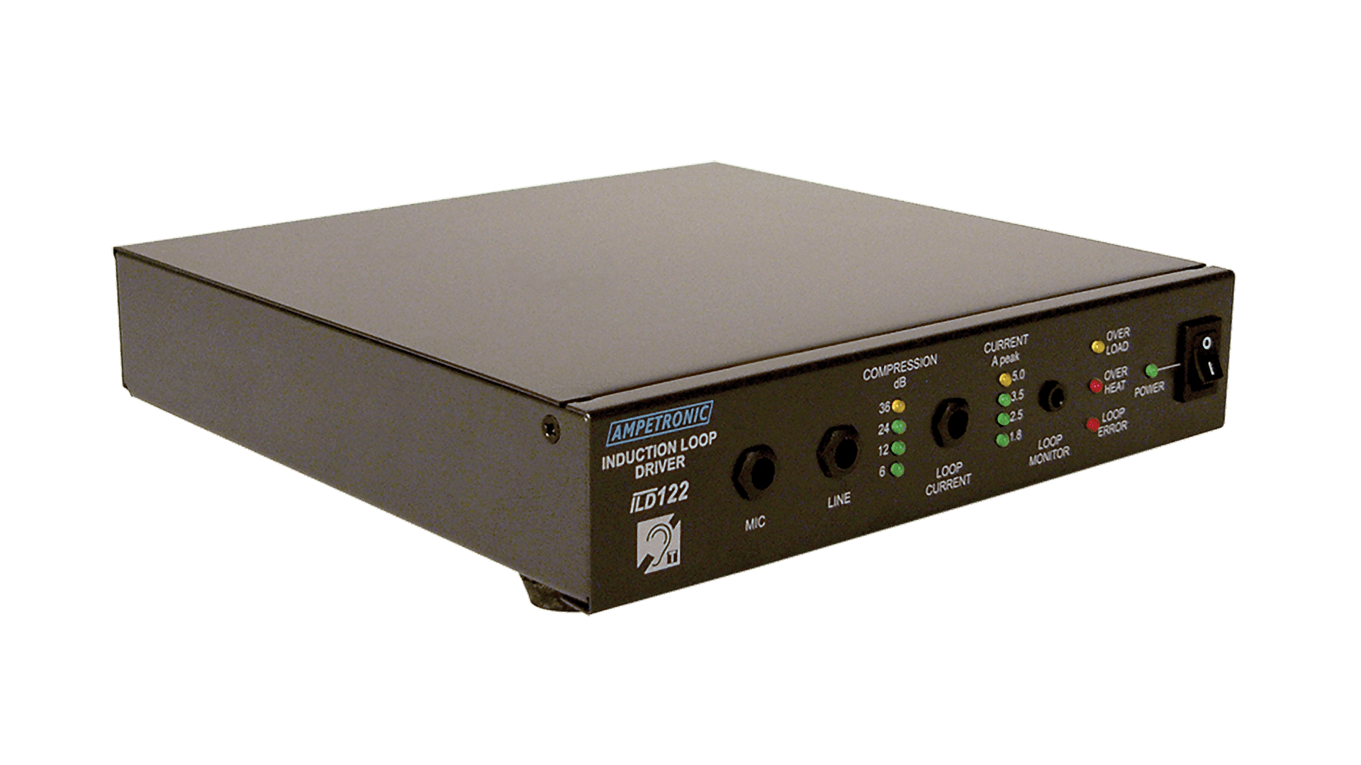
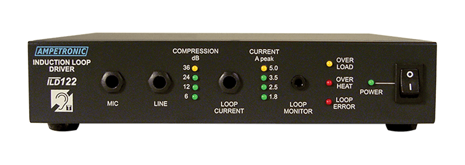
ILD122 Specifications
INPUTS
| Power |
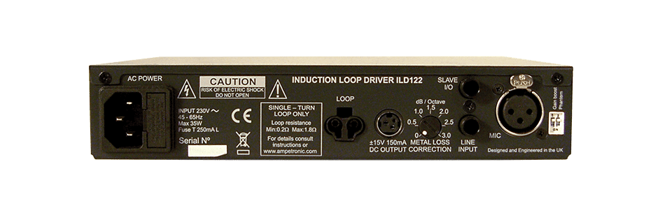
35 W 230 V AC nominal, 45-65 Hz [120 V option available]
Power switch and LED indicator on front panel |
| Microphone input |
XLR balanced microphone input for 200-600 Ω microphones;
15 dB user selectable gain boost; + 15 V DC phantom power (selectable); sensitivity – 70 dBu; front panel recessed gain control |
| Line input |
6.4 mm jack socket balanced line input; sensitivity – 30 dBu; overload protected; front panel recessed gain control |
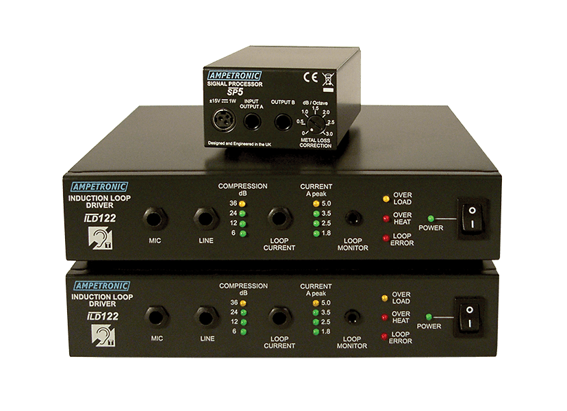
| Link I/O |
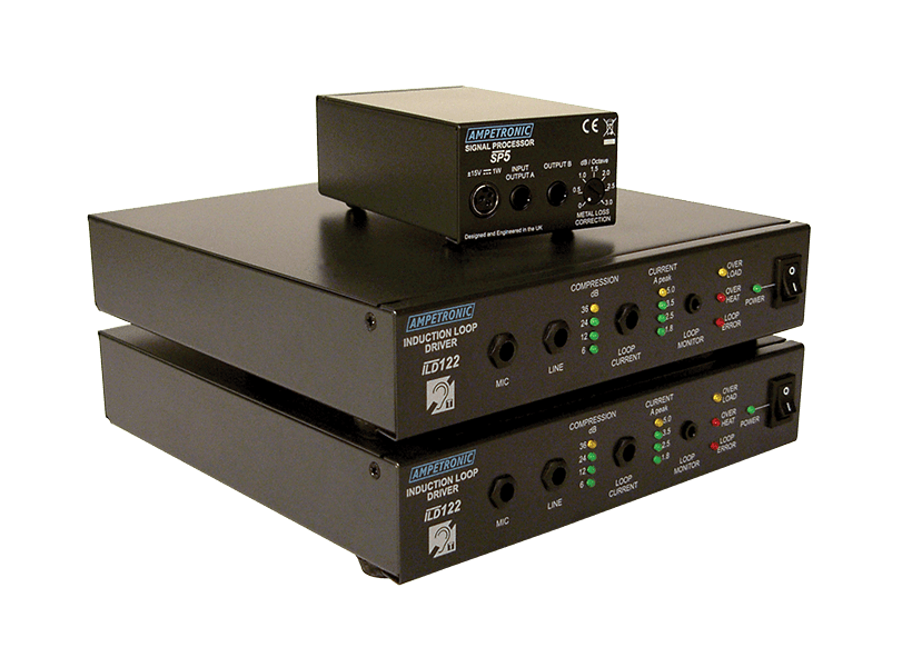
6.4 mm jack insert point for connection of SP5 phase shifter
0 dBu signal can be used for recording |
OUTPUTS
| Drive voltage |
8.5 Vrms (12V peak) at maximum output current |
| Drive current |
• 3.5 Arms (5 Apk) continuous 1 kHz sine wave
• Short term peaks >7 Apk
• Front panel recessed control
• Drive current indicated on 4-LED display in 3 dB increments |
| Loop connector |
Wieland ST17/2 (supplied) |
| Loop Monitor |
Provides access to actual audio signal in loop via a 3.5 mm stereo headphone connector on front panel |
AUDIO SYSTEM
| Freq. response |
80 Hz to 6.5 kHz |
| Distortion |
THD+N |
| Automatic Gain Control |
The AGC is optimised for speech. Range >36 dBu
Front panel recessed input level control |
| Metal loss correction |
Corrects system frequency response due to metal structures in a building. Gain constant at 1 kHz, adjustable gain slope from
0 to 3 dB per octave
This does not compensate for signal loss from metal structures, which can be significant |
ADDITIONAL FUNCTIONS
| Fault Monitoring |
Three LED fault indicators on the front panel:
• Overload – delivering over the rated current
• Overheat – unit is too hot (mutes output signal)
• Loop error – short circuit / open circuit error |
| Ancillary |
To supply Ampetronic ancillary units
±15 V DC 0.15 A power outlet on rear panel |
| Cooling |
Cooling is by natural convection from product casing |
PHYSICAL
| Dimensions |
Half width 1U 19″ rack mount
Width 215 mm Depth 220 mm Height 44 mm |
| Mounting options |
• Freestanding
• 1U 19″ rack mount (requires additional rack tray)
• Wall mounting (requires additional brackets) |
| Weight |
1.8kg |
| Environment |
IP 20 protection; 20 to 90% relative humidity; 0 to 35 ºC |


