


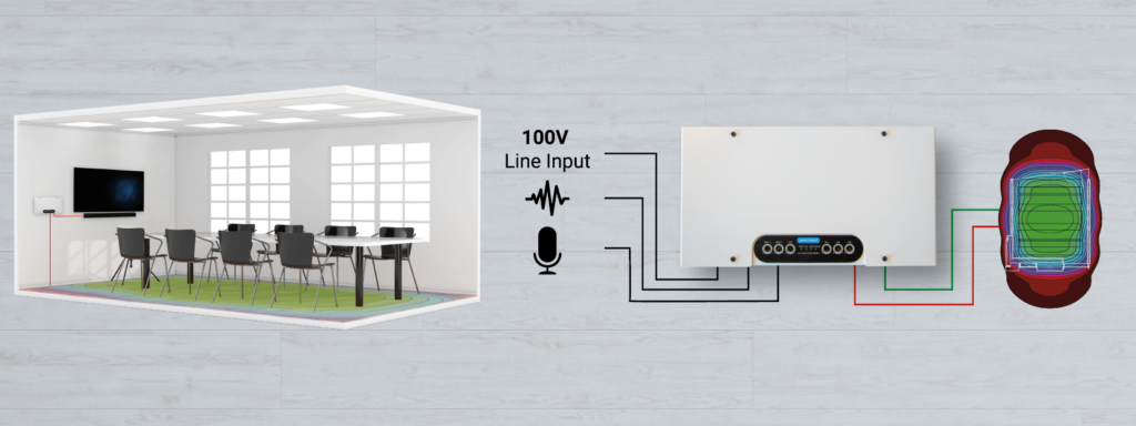
The W5-2 is designed particularly for small rooms where there is no AV rack and no network monitoring requirements, but can still make use of Ampetronic’s industry leading spill control design.
Design templates for low spill in especially small rooms are available to download from the Loopworks portal here. These are optimised specifically for the W5-2, including two turn options with twin core flat copper tape for higher loss environments.
Note that a Loopworks account is needed to access design template downloads, it is free to register and grants access to the full suite of Loopworks tools and resources.
Use the calculator below to find the most suitable design template for your room and determine the required cable length.


