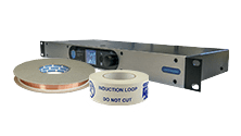
The following are examples of some of the errors that can be reported on Ampetronic induction loop amplifiers and their possible causes.
Many of these indicate a potential problem with the loop circuit or installation, rather than the amplifier itself, so all possible tests should be carried out on the installed cable before requesting a repair of the amplifier.
More specific troubleshooting information may be contained in the amplifier handbook. Digital amplifiers will give more detailed errors on screen or on the status page if connected to a network. If your error is not listed here, check the handbook or contact Ampetronic support.
If having followed all these steps the amplifier is still showing an error please follow our repairs procedure, or if you need assistance carrying out some of the recommended tests, please contact Ampetronic support with as much information as possible on the detail of the fault on +44 (0) 1636 610062 or email support@ampetronic.com
No Power LED Illuminated
- Check internal mains input fuse on the amplifier, replace if necessary. Ensure correct rating is used, most amplifiers have a fuse holder including a spare fuse in the AC Power inlet, otherwise consult the handbook for fuse location and rating
- Check power cable and fuse in plug if applicable, ensure power socket or supply is turned on
- Check amplifier power switch is toggled to the ON (I) position if applicable
Loop or Loop Error LED Illuminated / Message about Loop or Output A or B 10R, Open Circuit
Indicates the loop cable connected to the unit is outside specification. It is important that the total resistance of loop and feed are within the specified limits. In this state the relevant amplifier output will be disabled, if using a dual channel amplifier, the other output will still function as normal.
IMPORTANT: On analogue amplifiers, once the cause of any loop error has been established the unit will need to be restarted. Turn the power OFF – wait 5 seconds, and switch back ON.
- Check the loop is connected correctly, using a + and – terminal and the connector fully inserted into the amplifier loop output socket
- Check the loop has continuity and the DC resistance is within the limits stated in the handbook, the maximum range is 0.2 Ω to 10.0 Ω but varies per model (Normal operating resistance is 0.2 Ω to 3.0 Ω).
- Check resistance from the loop to ground, this should be open circuit or > 10 MΩ
- If using a Multiloop™ array, check resistance from one array circuit to the other, this should be open circuit
- Check the terminations of the loop are secure and untarnished, with no short circuits, at the loop connector and where feed cables connect to the loop
- If any of the above tests show a reading outside the acceptable range, then check for damage at obvious weak points such as joints between cable or tape. Also check for physical damage such as cuts by floor fitters and screws or bolts through tape
- A cable tracer may be required to accurately identify positions of breaks, however won’t necessarily show if there are more than two breaks in the loop circuit
Compression/AGC LEDs not Illuminating
- Check input connections
- Ensure the correct mic/line mode is selected, and phantom power enabled if required
- Check there is sufficient input signal level from the audio source and that the level control for the appropriate input is turned up
Current LEDs not Illuminating
- If any other errors are showing, follow the recommended steps for those first
- Check the CURRENT control is turned up sufficiently
- Check the COMPRESSION or AGC LEDs are illuminating
- Check all steps in the Loop Error section to ensure the loop cable is working correctly
- Ensure there is nothing plugged into any Slave I/O sockets, if there is remove this and retest
Overload LED Illuminated / Channel A or B Clipping / Power Limit – Derated
Indicates too much current is being delivered into the loop or that the output voltage is clipping. Occasional lighting of this indicator is normal on peaks of signal.
- Check the loop is not open circuit, short circuit or connected to ground
- Check the loop is within specified resistance limits
- Check CURRENT isn’t set too high
Overheat LED Illuminated / Temp Limit – Derated or Muted / Heatsink Too Hot Pls Switch Off
Indicates the internal heatsink is too hot.
- Check the loop is not open circuit, short circuit or connected to ground
- Check the installation provides sufficient ventilation to the amplifier
- Check nothing is blocking the free flow of air where fans are used for cooling
Power LED flashing continuously
Indicates a general error status.
- If any other errors are showing, follow the recommended steps for those first
- Switch off, remove all connections except LOOP and POWER, set all controls to minimum and switch back on
Interference from Loop on to other AV Equipment, Feedback or Instability
Most often caused by either the loop circuit being grounded, or a ‘ground loop’ within the AV system. If a ground loop is identified, the fix must be with the AV system itself rather than the induction loop. Be aware that interference on to musical instruments can be caused by normal loop signal and doesn’t necessarily indicate a fault, spill control measures should be used in the system design to avoid this.
- Check resistance from each loop circuit to ground, this should be open circuit or > 10 MΩ
- Disconnect audio inputs from the loop amplifier, test with internal test tones or battery powered signal generator
- Try disconnecting signal cables between AV equipment with remote power supplies, eg. projectors or powered speakers
- Check for any unbalanced signal cable runs near the loop circuit
- Make sure feed cable follows recommend twisted pair or starquad configuration


