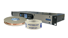
D14-2 networkable DSP hearing loop driver

D14-2 networkable DSP hearing loop driver
Part code: D14-2

The D14-2 networkable DSP hearing loop driver is now obsolete – please see C14-2 MultiLoop hearing loop driver

hidden tab
Features
  • Drives 2 output channels at 14ARMS each, featuring accurate and stable 90° phase shift
  • Networkable with remote browser interface
  • Built-in test tones – controllable with LoopLink
  • Digital display & intuitive ‘touch’ menu system
  • 3 menu modes; Main, Status & Quick
  • Highly energy efficient Class-D amplifier with low heat dissipation
  • Up to 2 x 1,300m2 Perimeter Loops area coverage
  • Up to 3,300m2 MultiLoop Low Loss area coverage
  • Compact 1U rack mount unit with internal transformer for simple rack installation
  • Optimised for speech frequencies with unmatched intelligibility & capable of high quality musical reproduction
  • AGC & Dual Slope MLC
  • Active status monitoring & remote fault reporting via email
  • Data compliant with: IEC 62489-1 Standard
Perimeter Loop Systems m2
Driver Metal Loss 1:1 Perimeter Loop 3:1 Perimeter Loop
D7-2 0dB 2 x ≤400 2 x ≤650
5dB Max 5m width Max 5m width
D10-1 0dB ≤1,000 ≤1,450
10dB Max 5m width Max 5m width
D10-2 0dB 2 x ≤1,000 2 x ≤1,450
-10dB Max 5m width Max 5m width
D14-2 0dB 2 x ≤1,300 2 x ≤1,450
-10dB Max 5m width Max 5m width


MultiLoop Array Systems m2
Metal Loss Non Overlap Multiloop Loss Control Multiloop Low Spill Multiloop
0dB D7-2 ≤1,765 2 x ≤400Max 5m width 2 x ≤650Max 5m width
-5dB D7-2 ≤576
D10-2 ≤625
D7-2 ≤961
D10-2 ≤1156
D7-2 ≤841
-10dB D14-2 ≤361 D10-2 ≤625 D10-2 ≤441
-15dB D14-2 ≤289 D14-2 ≤196


Indicative metal loss scenarios are based on: 0db = a building with no structural metal, -5dB = a building with reinforced concrete (re-bar) construction, and -10dB = a room with steel raised access floor tiles, -15dB = a room with steel decking or reinforced concrete and raised access floor tiles.

Multiloop area coverage calculations are based on the following assumptions: 1:1 room aspect ratio, 3mm2 copper tape laid at floor level, base current varies depending on solution employed.

Standards

This product is designed to form part of a system that can meet all of the requirements of the international loop performance standard IEC60118-4, and the relevant parts of BS7594. To fully meet requirements of these standards, correct design, installation, commissioning and maintenance are required.

All specification data has been compiled in accordance with IEC62489-1, the international standard for audio frequency induction loop equipment. Specification data should only be compared with data compliant to this standard.

This product is CE and RCM marked to all relevant safety and EMC standards, and is NRTL (ETL) approved for sale in North America.

Specifications (PDF)

Click here to open datasheet in a new tab

D14-2 networkable DSP hearing loop driver

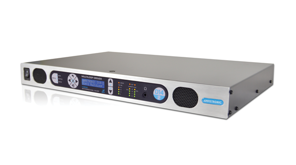
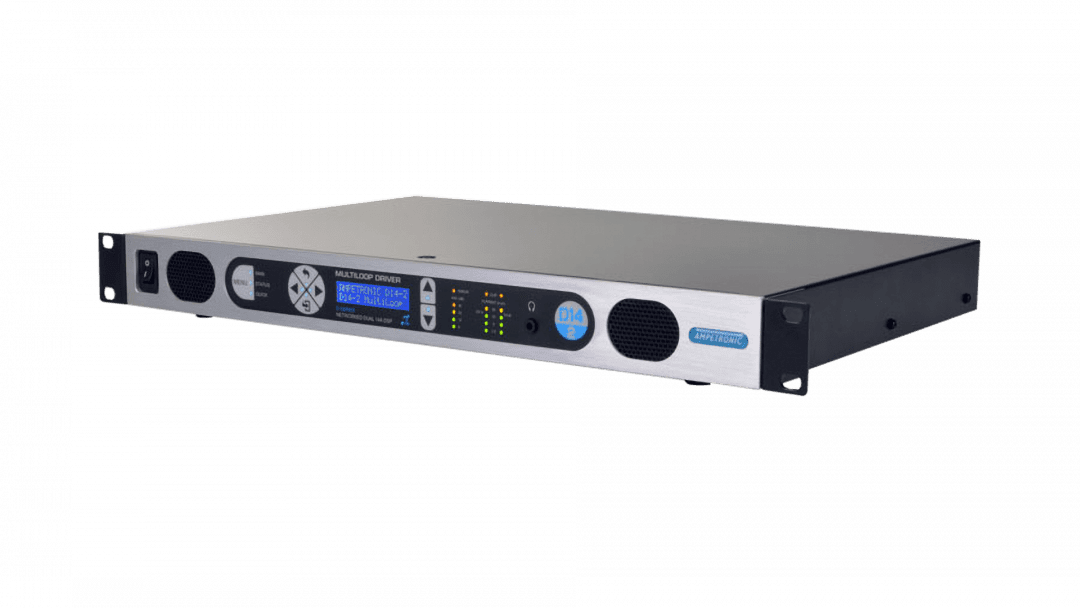
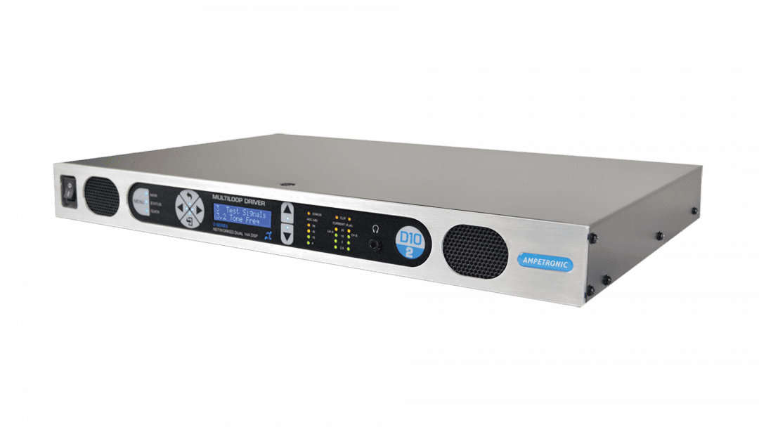
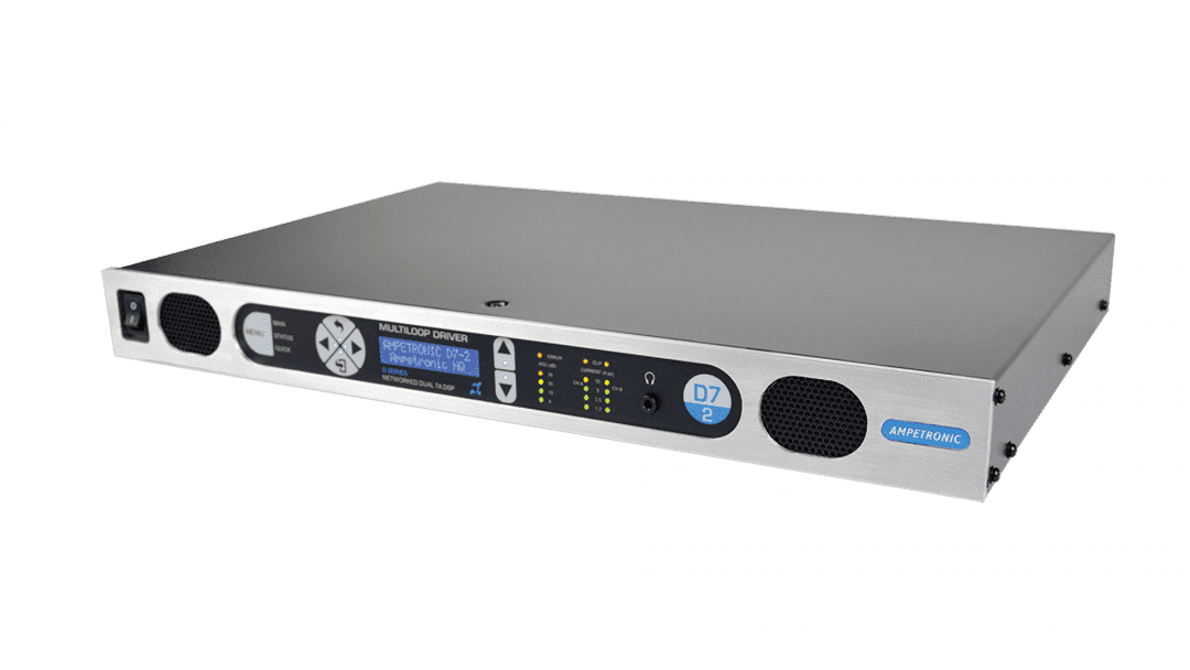
The D14-2 networkable DSP hearing loop driver represents the global benchmark for digital audio induction loop systems. The compact, elegant and sturdy units not only feature digital signal processing and networking functionality, but are also the most versatile and powerful solution available.

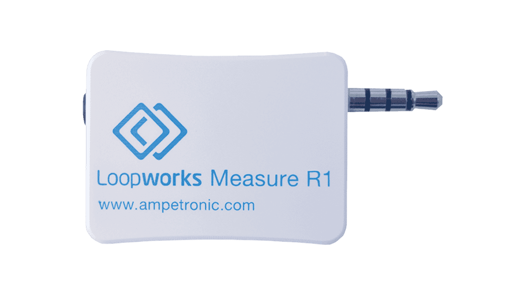
The D14-2 hearing loop amplifier is a 14 Amp dual output class 'D' driver; meaning a 60%+ increase in energy efficiency over existing solutions. Both drivers feature capacitive touch front panels with intuitive menus, built in test signals, and are fully networkable with a Wi-Fi accessible standard browser based control panel for remote set-up, monitoring and email alerts, and with Loopworks Measure LoopLink for easy test and commissioning.

The D14-2 networkable DSP hearing loop driver features 14 Amps per loop output plus ample voltage headroom, making it the most flexible solution on the market, suitable for a huge range of applications. The added power of the D14-2 provides a solution for installations in environments containing very high levels of metal, previously not possible without the use of combiners.

In another first for high-power Class D Induction Loop drivers, installation can be performed with total confidence, as unique multi-stage filtering ensures compatibility with both other system equipment and global EMC regulations. The D Series also boasts Dual slope Metal Loss Control that caters for a wide range of metal loss frequency characteristics.

Product Code:

The D14-2 networkable DSP hearing loop driver is now obsolete - please see C14-2 MultiLoop hearing loop driver

  • Drives 2 output channels at 14ARMS each, featuring accurate and stable 90° phase shift
  • Networkable with remote browser interface
  • Built-in test tones – controllable with LoopLink
  • Digital display & intuitive ‘touch’ menu system
  • 3 menu modes; Main, Status & Quick
  • Highly energy efficient Class-D amplifier with low heat dissipation
  • Up to 2 x 1,300m2 Perimeter Loops area coverage
  • Up to 3,300m2 MultiLoop Low Loss area coverage
  • Compact 1U rack mount unit with internal transformer for simple rack installation
  • Optimised for speech frequencies with unmatched intelligibility & capable of high quality musical reproduction
  • AGC & Dual Slope MLC
  • Active status monitoring & remote fault reporting via email
  • Data compliant with: IEC 62489-1 Standard
Perimeter Loop Systems m2
Driver Metal Loss 1:1 Perimeter Loop 3:1 Perimeter Loop
D7-2 0dB 2 x ≤400 2 x ≤650
5dB Max 5m width Max 5m width
D10-1 0dB ≤1,000 ≤1,450
10dB Max 5m width Max 5m width
D10-2 0dB 2 x ≤1,000 2 x ≤1,450
-10dB Max 5m width Max 5m width
D14-2 0dB 2 x ≤1,300 2 x ≤1,450
-10dB Max 5m width Max 5m width


MultiLoop Array Systems m2
Metal Loss Non Overlap Multiloop Loss Control Multiloop Low Spill Multiloop
0dB D7-2 ≤1,765 2 x ≤400Max 5m width 2 x ≤650Max 5m width
-5dB D7-2 ≤576
D10-2 ≤625
D7-2 ≤961
D10-2 ≤1156
D7-2 ≤841
-10dB D14-2 ≤361 D10-2 ≤625 D10-2 ≤441
-15dB D14-2 ≤289 D14-2 ≤196


Indicative metal loss scenarios are based on: 0db = a building with no structural metal, -5dB = a building with reinforced concrete (re-bar) construction, and -10dB = a room with steel raised access floor tiles, -15dB = a room with steel decking or reinforced concrete and raised access floor tiles.

Multiloop area coverage calculations are based on the following assumptions: 1:1 room aspect ratio, 3mm2 copper tape laid at floor level, base current varies depending on solution employed.

INPUTS

Power 50/80/160W 230V AC nominal, 45-65Hz [120V option available]
Power switch on front panel
Fuse values: D10-1 120V – T1.6AL | 230V – T1AL
Input 1 & 2
Programmable Microphone / Line
XLR balanced input switchable between microphone and line via menu

Microphone specification: 200 – 600 Ω, sensitivity -64dBu

Selectable 12V phantom power on microphone only

Line sensitivity: -39dBu

Input 2 can also be used for AES3 Digital Audio Signals

Link In 6.35mm jack socket for linking more than one amplifier.
Inserting plug disables other inputs

OUTPUTS

Loop Output Drive Voltage 33.9VRMS (48Vpk) at maximum output current per channel
Loop Output/Drive Current D7-X
•7ARMS (10Apk) up to 60 seconds continuous 1kHz sine
wave, peak >10A per channel
• Cont. pink noise 3.3ARMS short term peaks >10A per ch.D10-X• 10ARMS (14.1Apk) up to 60 seconds continuous 1kHz sine
wave, peak >14.1A per channel
• Cont. pink noise 4.7ARMS short term peaks >14.1A per ch.D14-X 
• 14ARMS (19.8Apk) up to 60 seconds continuous 1kHz sine
wave, peak >19.8A per channel
• Cont. pink noise 6.6ARMS short term peaks >20A per ch.
• Level controlled via front panel menu or network
• Drive current indicated on two 4-LED displays in 6dB increments
Link Out 6.35mm jack socket for linking more than one amplifier.
Loop Connectors Neutrik NL2 Speakons (supplied) for each output
Loop Monitor Provides access to monitor actual loop current via a
3.5mm stereo headphone connector on front panel
Channel A on left, channel B on right
DC Output Resettable, fuse protected 12V 0.1A. Operation can be
configured via menu.

THERMAL HEAT CHART

Idle 1/6 peak Output Current (Speech) 1/3 peak Output Current (Pink noise) Full Power
Driver Model Number of channels Current (Arms) Load Resistance (Ohms) AC In (W) BTU AC In (W) BTU AC In (W) BTU AC In (W) BTU
D14-2 2 14.0 0.44 23 78 41 107 90 176 317 493
D14-2 2 14.0 1.2 23 78 59 112 167 213 736 906
D14-2 2 10.0 2.4 23 78 52 85 141 117 560 273
D10-2 2 10.0 0.44 18.4 63 27 76 52 111 163 256
D10-2 2 10.0 1.2 18.4 63 36 76 88 118 337 331
D10-2 2 7.0 2.4 18.4 63 32 65 73 71 284 167
D10-1 1 10.0 0.47 13 44 17 49 30 67 91 150
D10-1 1 10.0 1.0 13 44 21 53 46 81 171 242
D10-1 1 7.0 2.0 13 44 19 46 41 66 156 198
D7-2 2 7.0 0.44 12 41 32 101 44 117 97 184
D7-2 2 7.0 1.0 12 41 35 101 60 130 191 317
D7-2 2 5.0 2.0 12 41 28 77 57 119 168 232


Audio System

Frequency Response: 80Hz to 6.5kHz
Distortion: THD+N <0.2% 1kHz sine at full current
Automatic Gain Control: The AGC is optimised for speech. Dynamic range >36dB
Metal Loss Correction: Corrects system frequency response due to metal structures in a building. Gain constant at 1kHz, adjustable gain slope from 0 to 4dB per octave in 0.25dB increments. Custom 2 slope MLC allows different slopes and transition frequency to be set via the menu.
This does not compensate for signal loss from metal structures which can be significant.
Phase Shift: User selectable at 0° or 90° between outputs

Additional Functions

Fault Monitoring:

Indicators on the front panel:

  • Clipping – delivering over the rated voltage (per channel)
  • Error – Check status in menu

Temperature and loop errors reported via the status menu

Cooling: Variable speed fan cooled. Front inlet, rear exhaust.

Physical

Size: Full width 1U 19” rack mount. Width: 430mm Depth: 290mm Height: 44mm
Mounting Options: Freestanding 1U 19” rack mount (brackets included)
Weight:

  • D14-2: 6.9kg
  • D10-2: 5.5kg
  • D10-1: 4.37kg
  • D7-2: 4.62kg

Environment: IP20 rated; 20 to 90% relative humidity; 0 to 35ºC


This product is designed to form part of a system that can meet all of the requirements of the international loop performance standard IEC60118-4, and the relevant parts of BS7594. To fully meet requirements of these standards, correct design, installation, commissioning and maintenance are required.

All specification data has been compiled in accordance with IEC62489-1, the international standard for audio frequency induction loop equipment. Specification data should only be compared with data compliant to this standard.

This product is CE and RCM marked to all relevant safety and EMC standards, and is NRTL (ETL) approved for sale in North America.

hidden tab
Features
  • Drives 2 output channels at 14ARMS each, featuring accurate and stable 90° phase shift
  • Networkable with remote browser interface
  • Built-in test tones – controllable with LoopLink
  • Digital display & intuitive ‘touch’ menu system
  • 3 menu modes; Main, Status & Quick
  • Highly energy efficient Class-D amplifier with low heat dissipation
  • Up to 2 x 1,300m2 Perimeter Loops area coverage
  • Up to 3,300m2 MultiLoop Low Loss area coverage
  • Compact 1U rack mount unit with internal transformer for simple rack installation
  • Optimised for speech frequencies with unmatched intelligibility & capable of high quality musical reproduction
  • AGC & Dual Slope MLC
  • Active status monitoring & remote fault reporting via email
  • Data compliant with: IEC 62489-1 Standard
Perimeter Loop Systems m2
Driver Metal Loss 1:1 Perimeter Loop 3:1 Perimeter Loop
D7-2 0dB 2 x ≤400 2 x ≤650
5dB Max 5m width Max 5m width
D10-1 0dB ≤1,000 ≤1,450
10dB Max 5m width Max 5m width
D10-2 0dB 2 x ≤1,000 2 x ≤1,450
-10dB Max 5m width Max 5m width
D14-2 0dB 2 x ≤1,300 2 x ≤1,450
-10dB Max 5m width Max 5m width


MultiLoop Array Systems m2
Metal Loss Non Overlap Multiloop Loss Control Multiloop Low Spill Multiloop
0dB D7-2 ≤1,765 2 x ≤400Max 5m width 2 x ≤650Max 5m width
-5dB D7-2 ≤576
D10-2 ≤625
D7-2 ≤961
D10-2 ≤1156
D7-2 ≤841
-10dB D14-2 ≤361 D10-2 ≤625 D10-2 ≤441
-15dB D14-2 ≤289 D14-2 ≤196


Indicative metal loss scenarios are based on: 0db = a building with no structural metal, -5dB = a building with reinforced concrete (re-bar) construction, and -10dB = a room with steel raised access floor tiles, -15dB = a room with steel decking or reinforced concrete and raised access floor tiles.

Multiloop area coverage calculations are based on the following assumptions: 1:1 room aspect ratio, 3mm2 copper tape laid at floor level, base current varies depending on solution employed.

Standards

This product is designed to form part of a system that can meet all of the requirements of the international loop performance standard IEC60118-4, and the relevant parts of BS7594. To fully meet requirements of these standards, correct design, installation, commissioning and maintenance are required.

All specification data has been compiled in accordance with IEC62489-1, the international standard for audio frequency induction loop equipment. Specification data should only be compared with data compliant to this standard.

This product is CE and RCM marked to all relevant safety and EMC standards, and is NRTL (ETL) approved for sale in North America.

Specifications (PDF)

Click here to open datasheet in a new tab

Book a demonstration

For more information on these products or any other requirement you may have, please complete the form or call us on +44 (0) 1636 610062

Click here to contact us for more information